Make Your Own Pressure-Activated Strobe Light
Every Halloween, I try to add some new skill to my arsenal. This year, it's electronics. If you're reading this before Halloween 2025 - no, I'm not telling you what the theme is - you'll have to come back!
My eldest is now of an age where we can work together on little projects, and has a decent enough understanding to follow along. So, I took a £5 'thunder and lightning' strobe box from B&M bargains, ignored the instructions to not take it apart, and hooked it up to a pressure plate.
The idea is that the pressure plate can sit underneath the doormat, so when trick-or-treaters come to knock on the door, it will trigger the strobe light and thunderclap noise and give a little fright. How devious!
🎥 Take a look at the finished build!
Let's jump into how I wired this all together.
Wiring
Here's the setup:
USB 5V
  ├─ Ardunio

Arduino 5V
  ├─ Relay (On trigger) DC+
  ├─ Relay (Off trigger) DC+

Arduino GND
  ├─ Pressure Plate Switch
  ├─ Relay (On trigger) DC-
  ├─ Relay (Off trigger) DC-

Arduino D2
  ├─ Pressure Plate

Arduino D3
  ├─ Relay (On trigger) IN

Arduino D4
  ├─ Relay (Off trigger) IN

Strobe Light +ve
  ├─ Relay (On trigger) COM
  ├─ Relay (Off trigger) COM

Strobe Light On Trigger
  ├─ Relay (On trigger) NO

Strobe Light Off Trigger
  ├─ Relay (Off trigger) NO
As a hand-drawn wiring diagram:
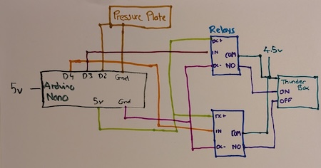
Let's break this down into the constituent parts:
Pressure Plate
The pressure plate is a simple switch, so it connects to the Arduino GND and a Digital pin. This lets me read the signal for when its pressed state changes.
For testing purposes, I've sellotaped some aluminum foil to cardboard and added some additional 'spacer' cardboard. When pressed, the foil touches, completing the circuit.
On the Arduino, I configure pin D2 to use an internal pull-up resistor, so that a reading of HIGH indicates that the switch is pressed, and conversely LOW means it's open.
                ----------------
 Arduino D2 <- | Pressure Plate | -> Arduino GND
                ----------------
Strobe Light
The strobe light originally had a three-way switch to choose from one of the following states:
- Flash lights and play sound
- Flash lights only
- Off
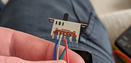
There were three terminals on the PCB corresponding to these states. The switch was also connected to the positive supply on the battery, so when the switch is moved to a position, the respective terminal receives a signal.
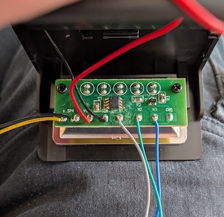
I only need the lights+sound and off terminals, so to control these from Ardunio I need a digital pin corresponding to each signal, and a relay to bridge the two. The strobe light will still be powered by its own battery supply, so all that's fundamentally changing is how that 'switch' happens.
                              --------------
               Relays COM <- | COM          |
    Relay (On trigger) NO <- | Light+Sound  |
   Relay (Off trigger) NO <- | Off          |
                             | Light        |
                              --------------
Relays
The two relays are powered from the Arduino's 5V output, with the return going to Arduino's GND. The trigger signal comes from one of the Arduino's digital pins - D3 for the 'light box on' signal, and D4 for the 'off'. As the strobe light remains powered by its own battery supply, the positive feed that was connected to the switch is now split and sent to the COM port on each relay.
The relay has two output options:
NO= normally openNC= normally closed
These correspond to the switch's default position - is it normally open (so an action 'closes' the switch) or normally closed (t'other way around). For what I need, NO is appropriate - when the relay is activated, the switch is closed. This completes the circuit to send the signal to the light box, to do something. If it was NC then they'd both immediately trigger!
                  ------------
   Arduino 5V <- | DC+     NO | -> Strobe Input
  Arduino GND <- | DC-     NC |
 Arduino DPin <- | IN     COM | -> Strobe +ve
                  ------------
Code
Arduino code is delightfully simple to write and well-documented. I connected my Arduino board to my PC via a USB cable - you need to make sure it's a cable that can do data transfer. The particular model I use is an ATmega328 minicore, which I installed via the Boards Manager in the Arduino IDE app.
This code reads the state of the pressure plate, and if it detects a press, will start a 12s activation of the strobe light box. Given the way the light box is controlled, my code 'pulses' the relays when it wants to send a command - turning them on and then off after a 200ms delay.
I've also added in some guard logic to only read the plate when needed, and to only send a single pressed signal if the plate is continuously pressed, which it will be if it's under a doormat.
Finally, for debugging purposes, the Arduino's built-in LED will light up to show that the signal to activate the strobe box has occurred.
const int platePin = 2;
const int relayMainPin = 3;
const int relayOffPin = 4;

const unsigned long durationMs = 12000;
const unsigned int offPulseMs = 200;
const unsigned int settleMs = 100;

unsigned long startMs = 0;
bool active = false;
bool lastState = LOW;

void setup() {
  pinMode(platePin, INPUT_PULLUP);
  pinMode(relayMainPin, OUTPUT);
  pinMode(relayOffPin, OUTPUT);
  pinMode(LED_BUILTIN, OUTPUT);

  digitalWrite(relayMainPin, LOW);
  pulseRelay(relayOffPin);
}

bool readPlate() {
  bool current = digitalRead(platePin);
  bool pressed = (lastState == LOW && currrent = HIGH);
  lastState = current;
  return pressed;
}

void set(int pin, bool on) {
  digitalWrite(pin, on ? HIGH : LOW);
}

void pulseRelay(int pin) {
  set(pin, true);
  delay(settleMs);
  set(pin, false);
}

void loop() {
  if (!active && readPlate()) {
    active = true;
    startMs = millis();
    pulseRelay(relayMainPin);
    set(LED_BUILTIN, true);
  }

  if (active && (millis() - startMs >= durationMs)) {
    pulseRelay(relayOffPin);
    set(LED_BUILTIN, false);
    active = false;
  }

  delay(50);
}
Component List
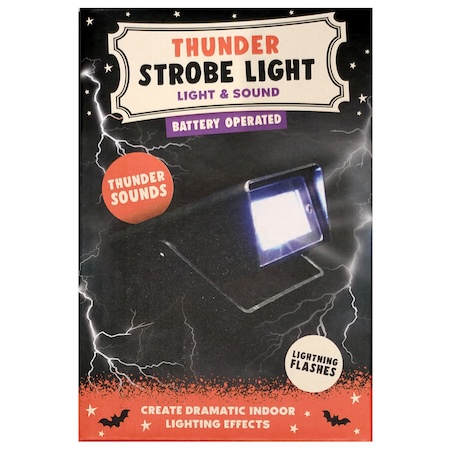
- Strobe and Thunder SFX Light
- Arduino Nano Board (pre-soldered headers, cos I'm lazy)
- Nano Extension Board (again, because I'm lazy)
- 5V Relays